Series: OGP 2 HP, 2875 RPM, 3 Phase, 50 Hz.
|
|
|
- Ulrik Bendtsen
- 10 år siden
- Visninger:
Transkript
1 INSTALLATION MANUAL Submersible Two-Stage Grinder Pump Series: OGP 2 HP, 2875 RPM, 3 Phase, 50 Hz. This product may be covered by one or more of the following patents and other patent(s) pending: US Patent 7,357,341 IMPORTANT! Read all instructions in this manual before operating pump. As a result of Crane Pumps & Systems, Inc., constant product improvement program, product changes may occur. As such Crane Pumps & Systems reserves the right to change product without prior written notification. A Crane Co. Company 420 Third Street 83 West Drive, Bramton Piqua, Ohio Ontario, Canada L6T 2J6 Phone: (937) Phone: (905) Fax: (937) Fax: (905) Form No Rev. D

2 ATTENTION SAFETY FIRST! Please Read This Before Installing Or Operating Pump. This information is provided for SAFETY and to PREVENT EQUIPMENT PROBLEMS. To help recognize this information, observe the following symbols: IMPORTANT! Warns about hazards that can result in personal injury orindicates factors concerned with assembly, installation, operation, or maintenance which could result in damage to the machine or equipment if ignored. CAUTION! Warns about hazards that can or will cause minor personal injury or property damage if ignored. Used with symbols below. WARNING! Warns about hazards that can or will cause serious personal injury, death, or major property damage if ignored. Used with symbols below. Hazardous fl uids can cause fi re or explosions, burnes or death could result. Biohazard can cause serious personal injury. Rotating machinery Amputation or severe laceration can result. Extremely hot - Severe burnes can occur on contact. Hazardous fl uids can Hazardous pressure, eruptions or explosions could cause personal injury or property damage. Hazardous voltage can shock, burn or cause death. Only qualifi ed personnel should install, operate and repair pump. Any wiring of pumps should be performed by a qualifi ed electrician. WARNING! - To reduce risk of electrical shock, pumps and control panels must be properly grounded in accordance with the National Electric Code (NEC) or the Canadian Electrical Code (CEC) and all applicable state, province, local codes and ordinances. WARNING! - To reduce risk of electrical shock, always disconnect the pump from the power source before handling or servicing. Lock out power and tag. Prevent large articles of clothing, large amounts of chemicals, other materials or substances such as are uncommon in domestic sewage from entering the system. During power black-outs, minimize water consumption at the home(s) to prevent sewage from backing up into the house. Always keep the shut-off valve completely open when system is in operation (unless advised otherwise by the proper authorities). Before removing the pump from the basin, be sure to close the shut-off valve. (This prevents backfl ow from the pressure sewer.) Keep the control panel locked or confi ned to prevent unauthorized access to it. If the pump is idle for long periods of time, it is advisable to start the pump occasionally by adding water to the basin. CAUTION! Pumps build up heat and pressure during operation-allow time for pumps to cool before handling or servicing. WARNING! - DO NOT pump hazardous materials (fl ammable, caustic, etc.) unless the pump is specifi cally designed and designated to handle them. Do not block or restrict discharge hose, as discharge hose may whip under pressure. WARNING! - DO NOT wear loose clothing that may become entangled in the impeller or other moving parts. WARNING! - Keep clear of suction and discharge openings. DO NOT insert fi ngers in pump with power connected. Make sure lifting handles are securely fastened each time before lifting. Do not operate pump without safety devices in place. Always replace safety devices that have been removed during service or repair. Do not exceed manufacturers recommendation for maximum performance, as this could cause the motor to overheat. Secure the pump in its operating position so it can not tip over, fall or slide. Cable should be protected at all times to avoid punctures, cut, bruises and abrasions - inspect frequently. Never handle connected power cords with wet hands. To reduce risk of electrical shock, all wiring and junction connections should be made per the NEC or CEC and applicable state or province and local codes. Requirements may vary depending on usage and location. Submersible Pumps are not approved for use in swimming pools, recreational water installations, decorative fountains or any installation where human contact with the pumped fl uid is common. Do not remove cord and strain relief. Do not connect conduit to pump. Products Returned Must Be Cleaned, Sanitized, Or Decontaminated As Necessary Prior To Shipment, To Insure That Employees Will Not Be Exposed To Health Hazards In Handling Said Material. All Applicable Laws And Regulations Shall Apply. Bronze/brass and bronze/brass fi tted pumps may contain lead levels higher than considered safe for potable water systems. Lead is known to cause cancer and birth defects or other reproductive harm. Various government agencies have determined that leaded copper alloys should not be used in potable water applications. For non-leaded copper alloy materials of construction, please contact factory. IMPORTANT! - Crane Pumps & Systems, Inc. is not responsible for losses, injury, or death resulting from a failure to observe these safety precautions, misuse or abuse of pumps or equipment. Other brand and product names are trademarks or registered trademarks of their respective holders. Barnes is a registered trademark of Crane Pumps & Systems Inc. 4/07 Alteration Rights Reserved 2

3 USER GUIDE Congratulations on your purchase of a Barnes UltraGRIND grinder pump system. With proper care and by following a few simple guidelines your grinder pump will give you many years of dependable service. Use and Care The UltraGRIND grinder pump station is designed to handle routine, domestic sewage. Solid waste materials should be thrown in the trash. While your station is capable of accepting and pumping a wide range of materials, regulatory agencies advise that the following items should not be introduced into any sewer either directly or through a kitchen waste disposal: Glass Metal Diapers Socks, rags or cloth Plastic objects (e.g., toys, utensils, etc.) Sanitary napkins or tampons In addition you must NEVER introduce into any sewer: Explosives Flammable Material Lubricating Oil and/or Grease Strong Chemicals Gasoline General Information Your home wastewater disposal service is part of a low pressure sewer system. The key element in this system is the Barnes UltraGRIND grinder pump station. The basin collects all wastewater from the house. The solids in the sewage are then ground to a small size suitable for pumping in the slurry. The grinder pump generates suffi cient pressure to pump this slurry from your home to the wastewater plant. Power Failure Your grinder pump cannot dispose of wastewater or provide an alarm signal without electrical power. If electrical power service is interrupted, keep water usage to a minimum. Warranty Your grinder pump is furnished with a warranty against defects in material or workmanship. A properly completed Start-Up/Warranty Registration form must be on fi le at the Barnes factory in order to activate your warranty. In addition your pump must be installed in accordance with the installation instructions. If you have a claim under the provisions of the warranty, contact your local Barnes Distributor. When contacting your representative for service, please include your station serial number, pump model number, and pump serial number. For future reference, record the following information: Station Serial No: Pump Model No: Pump Serial No: Local Distributor: Distributor Telephone: 3

4 PUMP SPECIFICATIONS: DISCHARGE... 1¼ LIQUID TEMPERATURE F (40 C) Continuous MOTOR HOUSING... Cast Iron ASTM A-48, Class 30 VOLUTE... Cast Iron ASTM A-48, Class 30 SEAL PLATE... Cast Iron ASTM A-48, Class 30 IMPELLERS Design vane, Splitter-Type, vortex, with pump out vanes on back side. Dynamically balanced, ISO G6.3 Material Bronze SHREDDING RING... Hardened 440C Stainless Steel Rockwell C-55 CUTTER... Hardened 440C Stainless Steel Rockwell C-55 SHAFT Stainless Steel SQUARE RING... Buna-N HARDWARE Series Stainless Steel PAINT... Air dry enamel, top coat SEAL Design... Single Mechanical, oil fi lled reservoir Material... Rotating Faces - Silicon-Carbide Stationary Faces - Silicon-Carbide Elastomer - Buna-N Hardware series stainless steel CORD ENTRY... Custom Molded, Quick Connected for sealing and strain relief POWER CORD... CSA/UL Approved 12/4 Type SOW/SOOW SPEED RPM, 50Hz SENSOR... 18/3 CSA/UL, Type SOW/SOOW UPPER BEARING: Design... Single Row, Angular Contact Ball Lubrication... Oil Load... Radial & Thrust LOWER BEARING Design... Single Row, Angular Contact Ball Lubrication... Oil Load... Radial & Thrust MOTOR Design... NEMA L, Oil Filled, Squirrel Cage Induction Insulation... Class F OPTIONAL EQUIPMENT... Additional Cord, Automatic to Manual Adapter Plug Kit, BSP Check Valve Kit, C-Channel Rail Check Valve Kit 3 PHASE... Dual voltage 230/400 50Hz, Requires overload protection to be included in control panel. NOISE EMISSION MAX... In-air, 74 db-a SUBMERGENCE... Max depth 25ft (7.6m) MARKINGS... CSA, CE OGP20Y2C inches (mm) 4

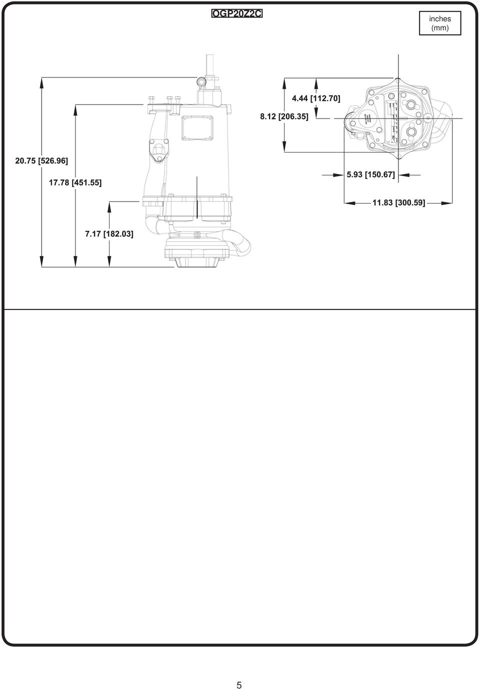
5 OGP20Z2C inches (mm) 5
6 MODEL NO PUMP WEIGHT lbs (Kg) HP VOLT PH Hz NEMA START CODE FULL LOAD AMPS LOCKED ROTOR AMPS CORD SIZE CODE TYPE CORD O.D. ±.02 (.5) in (mm) WINDING RESISTANCE OGP20Y2C 110 (49.9) K /4 SOOW.67 (17) 2.08 OGP20Z2C 110 (49.9) K /4 SOOW.67 (17) 6.24 Winding Resistance ± 5%, measured from terminal block. Pump rated for operation at ± 10% voltage at motor. Recommended Breaker Sizes Pump Model HP Phase Volts Breaker Size OGP20Y2C AMP OGP20Z2C AMP NOTE: Use with approved motor control that matches motor input in full load amperes with overload element(s) selected or adjusted in accordance with control instructions. The nameplate is located on top of the pump. This contains the pumps part number, horsepower voltage, phase, and serial number, as well as other information. The start-up form located in the back of this manual contains a place to record this data. The information should be recorded now so the pump does not have to be pulled again later. The start-up form can be left in the control panel until station start-up is completed later. Lifting Device: Attach lifting device Caution: Never lower or raise pump by cord! Tie the bowline knot where shown per the directions provided (Steps 1 through 5). On the CT (Not Shown) series tie bowline knot on the eyebolt. FIGURE 1 6
 selected or adjusted in accordance with control instructions. The nameplate is located on top of the pump.")
7 SERVICE: Lubrication: Anytime the pump is removed from operation, the cooling oil in the motor housing (4) should be checked visually for oil level and contamination. Checking Oil: Motor Housing - To check oil, set unit upright. Remove pipe plug (38) from motor housing (4). With a fl ashlight, visually inspect the oil in the motor housing (4) to make sure it is clean and clear, light amber in color and free from suspended particles. Milky white oil indicates the presence of water. Oil level should be just above the motor when pump is in vertical position. Testing Oil: 1.) Place pump on it s side, remove pipe plug (38), from motor housing (4) and drain oil into a clean, dry container. 2.) Check oil for contamination using an oil tester with a range to 30 Kilovolts breakdown. 3.) If oil is found to be clean and uncontaminated (measuring above 15 KV. breakdown), refi ll the motor housing as per section Replacing Oil. 4.) If oil is found to be dirty or contaminated (or measures below 15 KV. breakdown), the pump must be carefully inspected for leaks at the shaft seals (20), cord assemblies (37), square rings (13) and pipe plugs, (38) before refi lling with oil. To locate the leak, perform a pressure test as per section Pressure Test. After leak is repaired, dispose of old oil properly, and refi ll with new oil as per section Replacing Oil. Replacing Oil: Motor Housing - Drain all oil from motor housing and dispose of properly per Local and Environmental Standards. Set unit upright and refi ll with new cooling oil as per Table 1 (see parts list for amount). Fill to just above motor as an air space must remain in the top of the motor housing to compensate for oil expansion. Apply pipe thread compound to threads of pipe plug (38) then assemble to motor housing (4). TABLE 1 - COOLING OIL - Dielectric SUPPLIER GRADE BP Enerpar SE100 Conoco Pale Paraffi n 22 Mobile D.T.E. Oil Light G & G Oil Circulating 22 Imperial Oil Voltesso-35 Shell Canada Transformer-10 Texaco Diala-Oil-AX Woco Premium 100 Pressure Test: Pumps that have been disassembled, Motor Housing - If the pump has been disassembled, the oil should be drained before a pressure test, as described in section Checking Oil. Remove pipe plug (38) from motor housing (4). Apply pipe sealant to pressure gauge assembly and tighten into hole (See Figure 2). Pressurize motor housing to 10 P.S.I. Use soap solution around the sealed areas and inspect joints for air bubbles. If, after five minutes, the pressure is still holding constant, and no bubbles are observed, slowly bleed the pressure and remove the gauge assembly. Replace oil as described in section Replacing Oil. If the pressure does not hold, then the leak must be located and repaired. Figure 2: CAUTION! Pressure builds up extremely fast, increase pressure by tapping air nozzle. Too much pressure will damage seal. DO NOT exceed 10 P.S.I. Warning! - Do not overfill oil. Overfilling of motor housing with oil can create excessive and dangerous hydraulic pressure which can destroy the pump and create a hazard. Overfilling oil voids warranty. 7

8 RECEIVING/UNPACKING: Upon receiving the pump, it should be inspected for damage or shortages. If damage has occurred, fi le a claim immediately with the company that delivered the pump. Unpack pump and record pump serial and model number before installing. If the manual is removed from the packaging, do not lose or misplace. STORAGE: Short Term- For best results, pumps can be retained in storage, as factory assembled, in a dry atmosphere with constant temperatures for up to six (6) months. Long Term- Any length of time exceeding six (6) months, but not more than twenty-four (24) months. The units should be stored in a temperature controlled area, a roofed over walled enclosure that provides protection from the elements (rain, snow, wind-blown dust, etc.), and whose temperature can be maintained between +40 deg. F and +120 deg. F. If extended high humidity is expected to be a problem, all exposed parts should be inspected before storage and all surfaces that have the paint scratched, damaged, or worn should be recoated with a air dry enamel paint. All surfaces should then be sprayed with a rust-inhibiting oil. Pump should be stored in its original shipping container. On initial start up, rotate impeller by hand to assure seal and impeller rotate freely. If it is required that the pump be installed and tested before the long term storage begins, such installation will be allowed provided: 1.) The pump is not installed under water for more than one (1) month. 2.) Immediately upon satisfactory completion of the test, the pump is removed, thoroughly dried, repacked in the original shipping container, and placed in a temperature controlled storage area. 3.) Before placing pump into service, pump should be brought to operational temperature range. Excessive or direct heating or cooling should NOT be used. OPERATION TEMPERATURE RANGE: +35ºF (2ºC) to 104ºF (40ºC). SERVICE CENTERS: For the location of the nearest Barnes Service Center, check your Barnes representative or Crane Pumps & Systems, Inc. Service Department in Piqua, Ohio, telephone (937) or in Brampton, Ontario, Canada (905) INSTALLATION: Location - The pump is designed to fi t into your basin either by sliding down the rail assembly, or by being mounted on a pump base. THIS PUMP MUST BE INSTALLED WITH A MINIMUM OF 3 INCHES AND A MAXIMUM OF 4.5 INCHES OF CLEARANCE UNDER THE PUMP FOR THE ENTRANCE OF SEWAGE SOLIDS. FIGURE 3 - Normal Operating Points Discharge - Assemble discharge piping or hose assembly (whichever is required by your application), to the pump. Discharge piping should be as short as possible. Both a check valve and a shut-off valve are required for each pump being used. The check valve is used to prevent backfl ow into the sump. Excessive backfl ow can cause fl ooding and/ or damage to the pump. The shut-off valve is used to stop system fl ow during pump or check valve servicing. Package Systems- Refer to manual supplied with basin package system. ELECTRICAL CONNECTIONS: Pump Cables - The cord assembly mounted to the pump must NOT be modifi ed in any way except for shortening to a specifi c application. Any splice between the pump and the control panel must be made in accordance with the National Electric Code or the Canadian Electric Code and all applicable state, province and local electric codes. It is recommended that a junction box, be mounted outside the sump or be of at least Nema 4 (EEMAC-4) construction if located within the wet well. DO NOT USE THE POWER OR CONTROL CABLES TO LIFT PUMP! Thermal Protection The normally closed (N/C) over temperature sensor is embedded in the motor windings and will detect excessive heat in the event an overload condition occurs. The thermal sensor will trip when the windings become too hot and will automatically reset itself when the pump motor cools to a safe temperature. It is recommended that the thermal sensor be connected in series to an alarm device to alert the operator of an overtemperature condition and/or motor starter coil to stop pump. In the event of an overtemperature, the source of this condition should be determined and rectified immediately. 8
 months, but not more than twenty-four (24) months.")
9 Thermal protection shall not be used as a motor overload device. A separate motor overload device must be provided in accordance with NEC codes. DO NOT LET THE PUMP CYCLE OR RUN IF AN OVERLOAD CONDITION OCCURS! Wire Size - If additional cable is required consult a qualifi ed electrician for proper wire size. CABLE CONNECTIONS: Power/Control Cable- Insert female end of cable plug into housing bore aligning alignment mark with hole in terminal block see Figures 4 & 5. Tighten bolts on compression fl ange until fl ush with motor housing. Pump Power - Large Pin Temp Sensor - Small Pin FIGURE 4 FIGURE 5 - Automatic Pumps OGP20Y2C & OGP20Z2C 9

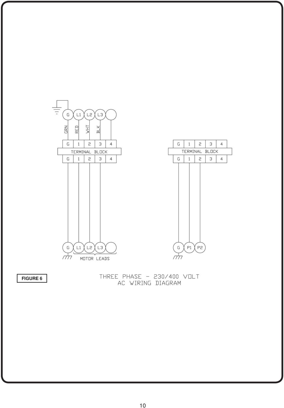
10 FIGURE 6 10
11 TROUBLE SHOOTING CAUTION! Always disconnect the pump from the electrical power source before handling. If the system fails to operate properly, carefully read instructions and perform maintenance recommendations. If operating problems persist, the following chart may be of assistance in identifying and correcting them: MATCH CAUSE NUMBER WITH CORRELATING CORRECTION NUMBER. NOTE: Not all problems and corrections will apply to each pump model. PROBLEM CAUSE CORRECTION Pump will not run 1. Poor electrical connection, blown fuse, tripped breaker or other interruption of power, improper power supply. 2. Motor or switch inoperative (to isolate cause, go to manual operation of pump). 2a. Float movement restricted. 2b. Switch will not activate pump or is defective. 3a. Insuffi cient liquid level. 3b. Switch is unable to activate Pump will not turn off Pump hums but does not run Pump delivers insuffi cient capacity Pump cycles too frequently or runs periodically when fi xtures are not in use Pump shuts off and turns on independent of switch, (trips thermal overload protector). CAUTION! Pump may start unexpectedly. Disconnect power supply. Pump operates noisily or vibrates excessively 2a. Float movement restricted. 2b. Switch will not activate pump or is defective. 4. Excessive infl ow or pump not properly sized for application. 9. Pump may be airlocked. 14. H-O-A switch on panel is in HAND position 1. Incorrect voltage 8. Cutter jammed or loose on shaft, worn or damaged, inlet plugged. 1. Incorrect voltage. 4. Excessive infl ow or pump not properly sized for application. 5. Discharge restricted. 6. Check valve stuck closed or installed backwards. 7. Shut-off valve closed. 8. Cutter jammed or loose on shaft, worn or damaged, inlet plugged. 9. Pump may be airlocked. 10. Pump stator damaged/torn. 6. Check valve stuck closed or installed backwards. 11. Fixtures are leaking. 15. Ground water entering basin. 1. Incorrect voltage. 4. Excessive infl ow or pump not properly sized for application. 8. Cutter jammed, loose on shaft, worn or damaged, inlet plugged. 12. Excessive water temperature. 4. Operating at too high a pressure. 5. Discharge restricted. 8. Cutter broken. 13. Piping attachments to buiding structure too rigid or too loose. 1. Check all electrical connections for security. Have electrician measure current in motor leads, if current is within ±20% of locked rotor Amps, impeller is probably locked. If current is 0, overload may be tripped. Remove power, allow pump to cool, then recheck current. 2a. Reposition pump or clean basin as required to provide adequate clearance for fl oat. 2b. Disconnect level control. Set ohmmeter for a low range, such as 100 ohms full scale and connect to level control leads. Actuate level control manually and check to see that ohmmeter shows zero ohms for closed switch and full scale for open switch. (Float Switch). 3a. Make sure liquid level is at least equal to suggested turn-on point. 3b. Rotate ESPS level control in horizontal position. 4. Recheck all sizing calculations to determine proper pump size. 5. Check discharge line for restrictions, including ice if line passes through or into cold areas. 6. Remove and examine check valve for proper installation and freedom of operation. 7. Open valve. 8. Check cutter for freedom of operation, security and condition. Clean cutter and inlet of any obstruction. 9. Loosen union slightly to allow trapped air to escape.verify that turn-off level of switch is set so that the suction is always fl ooded. Clean vent hole. 10. Remove & examine for damage. Replace pump stator if required. 11. Repair fi xtures as required to eliminate leakage. 12. Check pump temperature limits & fl uid temperature. 13. Replace portion of discharge pipe with fl exible connector. 14. Turn to automatic position. 15. Check for leaks around basin inlet and outlets. 11

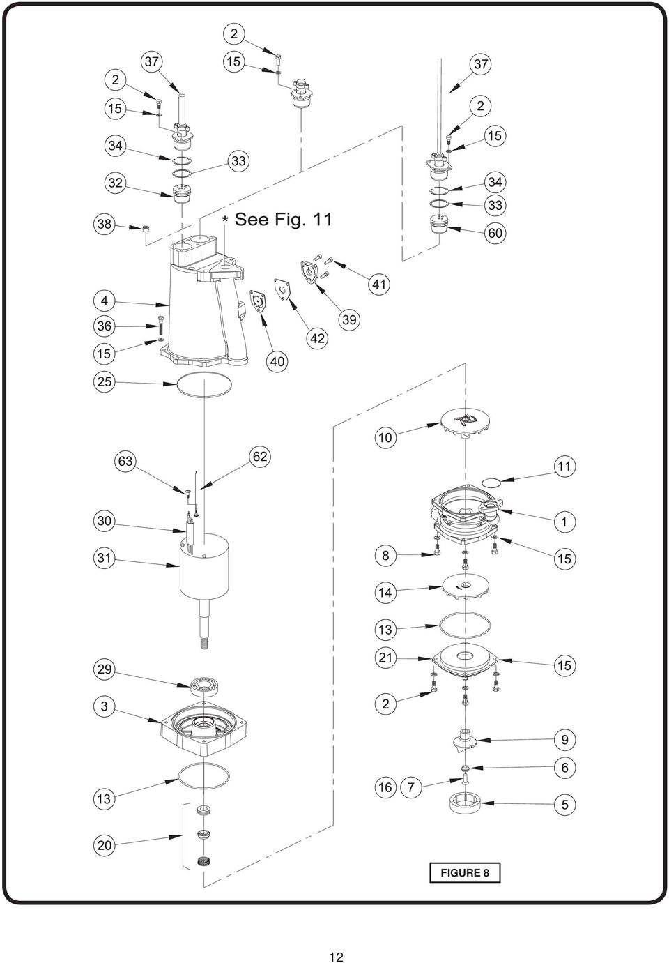
12 12 FIGURE 8
13 PARTS KITS Seal Repair Kit...P/N: Item # s: 6, 7, 13, 15, 20, 25, 33, 36, 38 Overhaul Kit... P/N: Item # s: 3, 5, 6, 7, 9, 13, 15, 20, 25, 28, 29, 33, 36, 38 Cutter Kit...P/N: Item # s: 5, 6, 7, 9, 13, 15, 36 PARTS LIST ITEM QTY PART NO. DESCRITION Volute Screw, 5/16-18 x.875 SS Seal Plate Motor Housing B Shredding Ring Washer Skhd Screw, 1/4-20 x.75 SS Skhd Screw, 5/16-18 x Radial Cutter Impeller, Second Stage O-Ring (-223) Square Ring Impeller, First Stage Lockwasher, 5/16 SS 16 A/R LOCTITE RC SD Seal, Silicon-Carbide (STD) A Suction Cover 24 A/R Cooling Oil - Mtr. Housing (Not Shown) Seal, Tetra Ball Bearing, Upper (Not Shown) Ball Bearing, Lower ITEM QTY PART NO. DESCRITION 30 1 or Sleeve Motor, 2HP, 230/400 Volt, 3 Phase (Includes items 28 & 29) Terminal Block, Power O-Ring Retaining Ring Screw, 5/16-18 x XC XC Cord, Set, 12/4, SOW, 30 Ft. Cord, Set, 14/3, SOW, 30 Ft Pipe Plug, C sunk, 3/8 NPT B Anti-Siphon Cover Gasket HXHD Screw 1/4-20 x.75 SS B Anti-Siphon Cover Plate Terminal Block, Temp Sensor Crimps ( D only) (Not Shown) Self-Tap 8-32 Screw Wire Assy, Ground Contact your local Distributor or the Factory for other cord lengths and other optional equipment. 13
 13 2 074793 Square Ring 14 1 125117 Impeller, First Stage 15 16 026322 Lockwasher, 5/16 SS 16 A/R 030237")
14 ITEM QTY PART NO. DESCRITION OGP20Y2C D Pump, OGP20Y2C, 50Hz Screw, SKHD, 5/16-18, Washer, Lock, 5/ Cardboard, Cover Sticker Instruction Sheet ITEM QTY PART NO. DESCRITION OGP20Z2C B Pump, OGP20Z2C, 50Hz Screw, SKHD, 5/16-18, Washer, Lock, 5/ Cardboard, Cover Sticker Instruction Sheet FIGURE 11 14

15 Limited 2 Year Warranty We warrant that products of our manufacture will be free of defects in material and workmanship under normal use and service for twenty-four (24) months after notice of owner s acceptance, but no greater than twenty-seven (27) months after receipt of shipment, when installed and maintained in accordance with our instructions. This warranty gives you specifi c legal rights, and there may also be other rights which vary from state to state. In the event the product is covered by the Federal Consumer Product Warranties Law (1) the duration of any implied warranties associated with the product by virtue of said law is limited to the same duration as stated herein, (2) this warranty is a LIMITED WARRANTY, and (3) no claims of any nature whatsoever shall be made against us, until the ultimate consumer, his successor, or assigns, notifi es us in writing of the defect, and delivers the product and/or defective part(s) freight prepaid to our factory or nearest authorized service station. Some states do not allow limitations on how long an implied warranty lasts, so the above limitation may not apply. THE SOLE AND EXCLUSIVE REMEDY FOR BREACH OF ANY AND ALL WARRANTIES WITH RESPECT TO ANY PRODUCT SHALL BE TO REPLACE OR REPAIR AT OUR ELECTION, F.O.B. POINT OF MANUFACTURE OR AUTHORIZED REPAIR STATION, SUCH PRODUCTS AND/OR PARTS AS PROVEN DEFECTIVE. THERE SHALL BE NO FURTHER LIABILITY, WHETHER BASED ON WARRANTY, NEGLIGENCE OR OTHERWISE. Unless expressly stated otherwise, guarantees in the nature of performance specifi cations furnished in addition to the foregoing material and workmanship warranties on a product manufactured by us, if any, are subject to laboratory tests corrected for fi eld performance. Any additional guarantees, in the nature of performance specifi cations must be in writing and such writing must be signed by our authorized representative. Due to inaccuracies in fi eld testing if a confl ict arises between the results of field testing conducted by or for user, and laboratory tests corrected for fi eld performance, the latter shall control. RECOMMENDATIONS FOR SPECIAL APPLICATIONS OR THOSE RESULTING FROM SYSTEMS ANALYSES AND EVALUATIONS WE CONDUCT WILL BE BASED ON OUR BEST AVAILABLE EXPERIENCE AND PUBLISHED INDUSTRY INFORMATION. SUCH RECOMMENDATIONS DO NOT CONSTITUTE A WARRANTY OF SATISFACTORY PERFORMANCE AND NO SUCH WARRANTY IS GIVEN. This warranty shall not apply when damage is caused by (a) improper installation, (b) improper voltage (c) lightning (d) excessive sand or other abrasive material (e) scale or corrosion build-up due to excessive chemical content. Any modifi cation of the original equipment will also void the warranty. We will not be responsible for loss, damage or labor cost due to interruption of service caused by defective parts. Neither will we accept charges incurred by others without our prior written approval. This warranty is void if our inspection reveals the product was used in a manner inconsistent with normal industry practice and\or our specifi c recommendations. The purchaser is responsible for communication of all necessary information regarding the application and use of the product. UNDER NO CIRCUMSTANCES WILL WE BE RESPONSIBLE FOR ANY OTHER DIRECT OR CONSEQUENTIAL DAMAGES, INCLUDING BUT NOT LIMITED TO LOST PROFITS, LOST INCOME, LABOR CHARGES, DELAYS IN PRODUCTION, IDLE PRODUCTION, WHICH DAMAGES ARE CAUSED BY ANY DEFECTS IN MATERIAL AND\OR WORKMANSHIP AND\OR DAMAGE OR DELAYS IN SHIPMENT. THIS WARRANTY IS EXPRESSLY IN LIEU OF ANY OTHER EXPRESS OR IMPLIED WARRANTY, INCLUDING ANY WARRANTY OF MERCHANTABILITY OR FITNESS FOR A PARTICULAR PURPOSE. No rights extended under this warranty shall be assigned to any other person, whether by operation of law or otherwise, without our prior written approval. A Crane Co. Company 420 Third Street 83 West Drive, Bramton Piqua, Ohio Ontario, Canada L6T 2J6 Phone: (937) Phone: (905) Fax: (937) Fax: (905)
 the duration of any implied warranties associated with the product by virtue of said law is limited to the same")
16 Notes 16

17 START-UP REPORT FOR SUBMERSIBLE PUMPS This form is designed to provide assurance that customer service and a quality product are the number one priority with Crane Pumps & Systems, Inc (CP&S). Please fi ll out the following questions as completely and accurate as possible. When complete, mail this form to: In U.S.A Send To: In Canada Send To: Crane Pumps & Systems, Inc Crane Pumps & Systems, Inc. Attn: Warranty Service Group Attn: Service Manager 420 Third Street 83 West Drive, Brampton Piqua, Ohio Ontario, Canada L6T 2J6 REPORTS THAT ARE NOT RETURNED CAN DELAY OR VOID WARRANTY. Pump Owner s Name: Address: Location of Installation Person in Charge Purchased From (Crane Pumps & Systems Representative/Distributor Phone Pump Model Serial No. Part Number Voltage Phase Hertz Horsepower Rotation: Direction of impeller rotation (Use C/W for clockwise, CC/W for counter-clockwise) Method used to check rotation (viewed from bottom) Does impeller turn freely by hand: Yes No Condition of equipment Good Fair Poor Condition of cable jacket Good Fair Poor Resistance of cable jacket Good Fair Poor Resistance of cable and pump motor (measured at pump control) Red-Black Ohms, Red-White Ohms, White-Black Ohms Resistance of Ground Circuit between Control Panel and outside of pump Ohms MEG Ohms check of insulation: Red to Ground White to Ground Black to Ground Condition of equipment at Start-Up: Dry Wet Muddy Was Equipment Stored? Length of Storage Describe station layout Liquid being pumped Debris in bottom of station? Was debris removed in your presence? Are guide rails exactly vertical? Is BAF stationary installed level? Liquid level controls: Model Are level controls installed away from turbulence? Operation Check: Tip lowest fl oat (Stop Float), All pumps should remain off. Tip second fl oat (and Stop Float), one pump comes On. Tip third fl oat (and Stop Float), both pumps on (alarm on simplex). Tip fourth fl oat (and Stop Float), high level alarm on (omit on simplex). If not CP&S level controls, describe type of controls Does liquid level ever drop below volute top? 17

18 CP&S control panel part no. and brand Number of pumps operated by control panel NOTE: At no time should holes be made in top of control panel, unless proper sealing devices are utilized. Control panel manufactured by others Company name Model number Short circuit protection Type Number and size of short circuit device(s) Amp rating Overload type Size Amp rating Do protection devices comply with pump and motor Amp rating? Are all connections tight? Is the interior of the panel dry? ELECTRICAL READINGS: Single Phase: Voltage supply at panel line connection, Pump Off, L1, L2 Voltage supply at panel line connection, Pump On, L1, L2 Amperage: Load connection, Pump On L1 L2 Three Phase: Voltage supply at panel line connection, Pump Off, L1 - L2 L2 - L3 L3 - L1 Voltage supply at panel line connection, Pump On, L1 - L2 L2 - L3 L3 - L1 Amperage: Load connection, Pump On L1 L2 L3 FINAL CHECK: Is pump seated on discharge properly? Check for leaks? Does check valve(s) operate properly? Flow, Does station appear to operate at proper rate? Pump down time Noise level: High Medium Low Comments: Equipment diffi culties during start-up: MANUALS: Has operator received pump instructions and parts manual? Has operator received electrical control panel diagram? Has operator been briefed on Warranty? Address of local CP&S Representative/Distributor: I have received the above information (Name of Operator) Name of Company I Certify this report to be accurate (Name of Start-Up person) Employed By: Date: Date: Date and time of Start-Up Present at Start-Up ( ) Engineer: ( ) Operator: ( ) Contactor: ( ) Other: To be filled out by factory: Start-Up form checked by: Date warranty registration mailed: 18

19 IMPORTANT! WARRANTY REGISTRATION Your product is covered by the enclosed Warranty. Complete the Warranty Registration Form and return to Crane Pumps & Systems, Inc. Warranty Service Group If you have a claim under the provision of the warranty, contact your local Crane Pumps & Systems, Inc. Distributor. FOLD HERE AND TAPE, DO NOT STAPLE **IMPORTANT!** WARRANTY REGISTRATION CUSTOMER S NAME DATE INSTALLED ADDRESS CITY STATE ZIP PHONE # FAX # DEALER S NAME CITY STATE ZIP MODEL NO. PART NO. SERIAL NO. BRAND 19

20 FOLD HERE AND TAPE, DO NOT STAPLE PLACE STAMP HERE CRANE PUMPS & SYSTEMS, INC. WARRANTY SERVICE GROUP 420 THIRD STREET PIQUA, OHIO U.S.A.

21 Monterings- og driftsvejledning Neddykket to-trins grinder pumpe Serie: OGP 1.5 KW, 2875 RPM, 3 faset, 50 Hz. VIGTIGT! Læs hele denne vejledning, inden pumpen tages i brug. Som et resultat af Crane Pumps & Systems, Inc. konstante produkt forbedrings program kan der forekomme ændringer på produktet. Derfor forbeholder Crane Pumps & Systems sig ret til at udføre ændringer på produket uden forudgående information. A Crane Co. Company 420 Third Street 83 West Drive, Bramton Piqua, Ohio Ontario, Canada L6T 2J6 Tlf.: (937) Tlf.: (905) Fax: (937) Fax: (905) Dok nr Rev. B
22 Sikkerhed kommer først! Nedenstående bør læses, inden pumpen installeres og tages i brug. Denne vejledning er udført for din sikkerhed og for at forhindre problemer med det leverede udstyr. Anvisningerne er i fl ere kategorier, der afmærkes som følger: VIGTIGT! Anføres ved advarslerer om forhold, der kan resultere i person skade, og ved vigtige faktorer vedrørende samling, installation, drift, eller vedligeholdelse, der - dersom de ignoreres - kan resultere i beskadigelse af pumpen eller udstyr den monteret i. FORSIGTIG! Anføres ved advarsler om forhold, der kan resultere i mindre person- og materiel skade, ifald de tilsidesættes; de markeres tillige med nedenstående faretavler. ADVARSEL! Anføres ved advarsler om forhold, der kan resultere i alvorlig personskade, livsfare, eller stor materiel skade, ifald de ignoreres; de markeres tillige med nedenstående faretavler. Farlige væsker kan forårsage brand og eksplosion, forbrænding og livsfare. Biologiske farer kan forårsage alvorlig personskade. Roterende dele. Risiko for lemlæstelse og svære læsioner. Meget varme dele - berøring kan give svære forbrændinger. Farlige væsker kan danne overtryk, oversprøjtning og eksplosion, der forårsager person- og materiel skade. Højspænding kan forårsage chok, forbrænding og dødsfald. Kun uddannet personale må installere, betjene eller reaparere pumperne. El-tilslutning skal udføres af autoriseret installatør. ADVARSEL! - Pumper og betjeningspaneler skal jordforbindes korrekt iht. gældende regulativ som forebyggelse mod elektrisk stød. ADVARSEL! - Strømmen skal altid afbrydes til pumpen forud for håndtering og reparation. Lås afbryderen og sæt passende afmærkning på den. Undgå at store stykker stof, store mængder af kemikalier eller andre materialer og ting, der normalt ikke forekommer i husholdningsspildevand, kommer i systemet. I tilfælde af strømafbrydelse bør man minimere vandforbruget, så spildevandet ikke hober sig op i afl øbsrørene.afspærringsventilen skal altid være fuldt åben når pumpen er i drift. Før pumpen fjernes fra pumpebrønden, skal afspærringsventilen lukkes for at forhindre tilbageløb fra trykledningen. Hold styreskabet afl åst for at forhindre uautoriseret adgang. Hvis pumpen er ubenyttet i lange perioder, anbefales det at starte pumpen med jævne mellemrum ved at tilsætte vand til pumpebrønden. FORSIGTIG! Pumpen udvikler varme og tryk under drift. Derfor tillad pumpen at afkøle før håndtering og service. ADVARSEL! - PUMP IKKE farlige væsker (brændbare, ætsende, og lignende) medmindre pumpen er specielt konstrueret og godkendt til dette. OGP pumpen er IKKE godkendt til dette. Trykafgangen må ikke blokeres eller indsnævres. ADVARSEL! - BÆR ALDRIG løsthængende tøj der kan gribe fat i skæresystemet eller andre roterende dele. ADVARSEL! - Stik ikke fi ngrene ind i afgangsstudsen eller i nærheden af knivsystemet, med strømmen tilsluttet. Kontrollér at løfte udstyr er forsvarligt fastgjort før løft. Kun godkendt løfteudstyr må anvendes til løft af pumpen. Start aldrig pumpen uden alle sikkerhedsanordninger er på plads. Husk altid at montere, eller hvis nødvendigt udskifte, sikkerhedsanordninger efter service eller reperation. Vær sikker på at pumpen kører indenfor det anbefalede driftområde. Fastgør pumpen forsvarligt i driftpositionen, så den hverken kan tippe, glide eller falde ned under drift. Fastgør kablet i toppen af pumpebrønden, således at brud eller slid på kablet undgås. Undersøg kablet med jævne mellemrum. Rør aldrig ved el-kablet med våde hænder. Alt el-arbejdet skal udføres af en autoriseret elinstallatør, og i henhold til gældende regulativ. Pumpen må ikke være tilsluttet elforsyningen ved montage. Dykpumper er ikke godkendt til brug i svømmebassiner, springvand eller andre installationer, hvor personer kan komme i kontakt med pumpevæsken. Fjern ikke løftekæde elle vire til ophejsning af pumpen. Forbind ikke pumpen til vandforsynings rørledninger. Returnerede produkter skal være rengjorte, desinfi cerede og forureningsfri før forsendelse. Dette skal sikre, at vore medarbejderne ikke udsættes for nogen smittefare ved håndtering af pumperne. Relevante love og regulativ om transport og håndtering af forurenede produkter skal overholdes. Bronze-, messing- og andre rødgodsdele i pumper kan indeholde bly i større mængde end hvad der betragtes som sikkert i drikkevand. Bly vides at fremkalde kræft, fødselsdefekter og anden forplantningsskade. Diverse myndigheder har bestemt, at blyholdige kobberlegeringer ikke bør benyttes til drikkevandsinstallationer. Data om sammensætningen af kobberlegeringskomponenter uden bly fås ved henvendelse til fabrikken. VIGTIGT! - Crane Pumps & Systems Inc. eller Liqfl ow er ikke ansvarlig for tab, tilskadekommelse eller død, som følge af manglende overholdelse af ovennævnte sikkerhedsforanstaltninger, misbrug eller forkert brug af pumpen eller andet udstyr. Andre mærke og produktnavne er varemærker eller registrerede varemærker tilhørende de respektive ejere. Barnes er et registreret varemærke fra Crane Pumps & Systems Inc. 4/07 Ret til ændringer forbeholdes. 22
23 Brugsanvisning tillykke med dit køb af en Barnes grinder pumpe. Med den rigtige vedligeholdelse og brug af et par få simple vejledninger, vil denne grinder pumpe give dig mange års pålidelig drift. Brug og omsorg Grinder pumper er konstrueret til at håndtere normal husholdningsspildevand. Fast affald skal smides i affaldsspanden og ikke i toilettet. Pumpen er dog i stand til at håndtere en lang række materialer, men det anbefales at undgå at følgende materialer kommer med i kloakken. Glas Metal Bleer, håndklæder og gulvklude Sokker, reb og tøj Plastik emner (f.eks., legetøj, kuglepenne o.l.) Hygiejnebind og tamponer Derudover må der ALDRIG ledes følgende ud i kloakken. Eksplosive væsker Brændbare materialer og væsker Smøreolie og fedt Stærke kemikalier Benzin Generel information Dit private spildevandssystem er en del af et tryksat spildevandssystem. Hovedelementet i dette er grinder pumpestationen. Pumpebrønden opsamler spildevandet fra huset. Partiklerne i spildevandet skæres med pumpens grinder system i meget små stykker, således at det er muligt at pumpe disse igennem trykledningen. Grinder pumpen genererer tilstrækkelig tryk, således det er muligt at pumpe spildevandet fra dit hjem til det kommunale spildevandssystem. Strøm udfald Din grinder pumpe kan ikke pumpe spildevand eller give en alarm uden strøm. Derfor i tilfælde af strøm udfald anbefales det at forbruge mindst muligt vand. Garanti Din grinder pumpe er dækket af en garanti der omfatter fejl ved produktet. For at aktivere garanti perioden skal pumpen registreres hos din lokale forhandler. Derudover skal det sikres at pumpen er installeret i henhold til installations vejledningen. Hvis der er problemer med produktet, kontakt da venligst din lokale forhandler. Ved kontakt med forhandler vedrørende service, bedes oplyst pumpe type og serie nummer. Til fremtidig brug, udfyld venligst nedenstående information: Station serie nr: Pumpe model: Pumpe serie nr: Lokal forhandler: Forhandler telefon nr: 23
24 PUMPE SPECIFIKATIONER: TRYKAFGANG... 1¼ NPT, vertikal, med løsfl ange VÆSKE TEMPERATUR C ved kontinuerlig drift MOTOR HUS... Støbejern EN-JL1040 PUMPEHUS... Støbejern EN-JL1040 AKSELTÆTNINGS PLADE Støbejern EN-JL1040 LØBEHJUL Type vinget, fristrøm, med vinger på bagsiden. Dynamisk afbalanceret ISO G6.3 Materiale Bronze STATIONÆR KNIV... Hærdet 440C rustfrit stål... Rockwell C-55 ROTERENDE KNIV... Hærdet 440C rustfrit stål... Rockwell C-55 AKSEL rustfrit stål O-RINGE... Buna-N STÅL serie rustfrit stål MALING... Pulvermaling, farve PMS 307, blå AKSEL TÆTNING Type... Mek. akseltætning i oliefyldt resorvoir Materiale... Roterende del - Siliciumkarbid Stationær del - Silliciumkarbid Gummidele - Buna-N Stål dele i 300 serie rustfrit stål KABEL GENNEMFØRING. Hermetisk lukket kabel stik, for tætning og nem montage/afmontering KABEL... Sort polyethylene gummmi kabel Type SOW/SOOW RPM RPM, 50Hz SENSOR KABEL... Sort polyethylene gummmi kabel Type SOW/SOOW ØVERSTE LEJE: Type... Enradet, vinkel kontakt kugleleje Smøring... Olie Belastning... Radiel og aksiel NEDERSTE LEJE Type... Enradet, vinkel kontakt kugleleje Smøring... Olie Belastning... Radiel og aksiel MOTOR Type... NEMA L, Olie fyldt, kortslutningsmotor Isolation klasse F EKSTRA UDSTYR... Ekstra kabel længder, ventiler, fi ttings, løftekæde m.m. 3 FASET... Spænding 230/400 50Hz. Motorværn... skal monteres i styretavle. STØJ... Max i luft, 74 db-a INSTALLATIONSDYBDE... Max 7,6 m under vandoverflade GODKENDELSER... CSA, CE OGP20Y2C mm
25 OGP20Z2C mm
26 PUMPE TYPE VÆGT KG P2 KW SPÆN- DING V Hz START METODE I nom A I start A KABEL STR. KABEL TYPE KABEL UDV. DIA. ± 0.5 mm VIKLINGS MODSTAND Ω OGP20Y2C x K /4 SOOW.67 (17) 2.08 OGP20Z2C x K /4 SOOW.67 (17) 6.24 Viklingsmodstand ± 5%, målt på klemrækken. Opgivne modstandsværdier i tabellen, inkluderer ikke modstand i kabel. Pumpe er designet til drift ved +6% / -10% af opgivne spænding. Anbefalet sikringsstørrelse Pumpe type P2 kw Faser Spænding Sikrings størrelse OGP20Y2C A OGP20Z2C A Typeskiltet er placeret på toppen af pumpen. Dette indeholder pumpens produkt nummer, motoreffekt, spænding, faseantal og serienummer, såvel som andre data. Registrerings formularen bag i denne manual indeholder felter til notering af disse data. Informationen bør noteres før montage af pumpen, således man ikke behøver at hejse pumpen op for at se disse data. Registreringsformularen kan lægges i styreskabet. TYPESKILT (Eksempel) Montage af løftekæde Løfte udstyr: Brug altid løftekæde Vigtigt: Løft ALDRIG pumpen i motor kablet! Fastgør løftekæden ved hjælp af en sjækel eller karabinhage, til løfteøjet på pumpen, som vist på tegningerne. FIGUR 1 26
27 SERVICE: Smøring: Hver gang pumpen fjernes fra installationen, skal olien i motor huset kontrolleres visuelt (4) for olie niveau og forurening. Olie inspektion: Motor hus - for at kontrollere olien skal pumpen stå oprejst. Fjern proppen (38) fra motorhuset (4). Brug en lommelygte til visuelt at kontrollere olien i motorhuset (4) for at konstatere om olien er ren og klar, lys i farven og fri for urenheder. Mælke hvid olie indikerer at olien indeholer vand, og pumpen bør efterses. Olie niveauet skal være lige over motoren når pumpen står i oprejst position. Teste olien: 1.) Placer pumpen på siden, og fjern proppen (38), fra motor huset (4). Aftap herefter olien i en ren bakke. 2.) Kontrolller olien for urenheder med en olie tester med et arbejdsområde op til 30 kilovolt. 3.) hvis olien er ren (måling på ca. 15kV) hæld da olien tilbage i pumpen, som beskrevet i afsnit udskiftning af olie ). 4.) Hvis olien ikke er ren (en måling under 15 kv), skal pumpen grundigt efterses for lekage ved akseltætningen (20), kabel samlinger (37), o-ringe (13), og olie prop (38), før pumpen fyldes med olie. For at fi nde en eventuel lekage, udfør da en trykprøvning som beskrevet i afsnit trykprøvning. Efter at pumpene er repareret, fyldes pumpen igen med olie som beskrevet afsnit Udskiftning af olie. Den brugte olie skal bortskaffes på forsvarlig vis. Udskiftning af olie: Motor hus - Aftap olien fra motorhuset og bortskaf denne forsvarligt i henhold til lokale forskrifter. Placer pumpen i oprejst position og påfyld ny olie som beskrevet i tabel 1 (se stykliste for mængden af olie). Fyld op til lige over motoren da der skal være lidt plads til at kompensere for oliens udvidelse under drift. Forsyn olie proppen (38) med pakgarn før den igen skrues i motorhuset (4). TABEL 1 - KØLE OILE - Elektrisk isolerende LEVERANDØR KVALITET Shell Shell Diabla DX Statoil Voltway N 7 X Q8 Michelangelo S YX Transformer oil inhibited Tryk prøvning: Pumper og motorhuse der har været adskilt - Hvis pumpen har været adskilt, skal pumpen tømmes for olie, som beskrevet i afsnit (Olie inspektion), før trykprøvning. Fjern olie proppen (38) fra motorhuset (4). Forsyn trykprøvnings kittet med pakgarn og skru det i hullet for olieproppen (Se Figur 3). Sæt tryk på motorhuset op til 10 P.S.I. Brug sæbevand omkring de tætnede områder og undersøg for luft bobler. Hvis trykket efter fem minutter stadig er konstant, og ingen luft bobler er observeret, da fjern forsigtigt trykprøvnings kittet. påfyld olie som beskrevet i afsnittet udskiftning af olie. Hvis trykket ikke holder, må lækagen findes og repareres. Advarsel! Trykket opbygges ekstremt hurtigt. Vær derfor meget forsigtig ved trykprøvningen. For stort tryk kan ødelægge akseltætningen. MAX TRYK er 10 P.S.I. 10 PSI LUFT TRYK MANOMETER KIT (SE STYKLISTE) Advarsel! - Motoren må aldrig overfyldes med olie. Hvis motoren overfyldes med olie, kan der opstå et usædvanligt og farligt højt hydraulisk tryk, som kan ødelægge pumpen og forårsage fare. Hvis motoren overfyldes bortfalder garantien. FIGUR 2 27
28 MODTAGELSE OG UDPAKNING: Ved modtagelse skal pumpen undersøges for beskadigelse under transport. Hvis pumpen er beskadiget skal det straks meddeles fi rmaet der har leveret pumpen. Pak pumpen ud og registrer pumpens serie nummer og type før installation. Opbevar instruktionen på et sikkert sted så den ikke bliver ødelagt. ALARM NIVEAU PUMPE 2 START NIVEAU PUMPE 1 START NIVEAU LAGRING: Kortvarigt- For at opnå det bedste resultat skal pumpen skal pumpen opbevares i original emballage, i en tør atmosfære og med konstant temperatur i op til 6 måneder. STOP NIVEAU Langvarigt- ved lagring i mere end 6 måneder og ikke mere end 24 måneder, skal pumpen opbevares i et temperatur kontrolleret rum, beskyttet imod regn, sne, vind støv og lignende. Rum temperaturen ved opbevaring skal være imellem 5 ºC og 50 ºC. Hvis ekstrem høj luft fugtighed kan forekomme under lagring, skal pumpen undersøges og eventuelle skader eller ridser i malingen skal udbedres. Pumpen skal derefter sprøjtes med en rustbeskyttende olie. Pumpen skal opbevares i original emballage. Ved montage af pumpen skal man sikre sig at løbehjulet og skæresystemet kan rotere frit. Hvis det kræves at pumpen installeres og testes lang tid før opstart, skal følgende sikres: 1.) At pumpen ikke er installeret under vand i mere end én måned uden at være i drift. 2.) At pumpen straks ved afslutnning af testen, fjernes fra installationen, tørres forsvarligt og pakkes i original em ballage, før den placeres i et temperatur kontrolleret lager rum. DRIFT TEMPERATUR OMRÅDE: 2ºC til 40ºC. SERVICE CENTER: For at fi nde dit nærmeste Barnes pumpe service center, check dit Barnes pumpe katalog eller kontakt Liqfl ow på på telefon eller info@liqfl ow.dk INSTALLATION: Pumpen er kontrueret til at passe i din pumpebrønd, enten ved guiderør montage, fritstående eller med beslag for hængekobling. Der fi ndes specielt fremstillede beslag til montage af pumpen i ovenstående udførsler. Kontakt Liqfl ow på telefon for nærmere information. DENNE PUMPE SKAL MONTERES MED MINIMUM AFSTAND TIL BUNDEN AF PUMPEBRØNDEN PÅ 75 MM OG HØJEST 110 MM, FOR AT SIKRE PARTIKLER FRI ADGANG TIL SKÆRESYSTEMET. Trykafgang - Monter trykrør eller slange (afhængig af hvad der kræves i diin installation), til pumpen. Trykrøret skal være så kort som muligt. Der skal monteres både kontraventil og afspærringsventil for hver pumpe der installeres. Kontraventilen sikrer at vandet fra trykrøret ikke løber FIGUR 3 - Normale drift niveauer BUND AF PUMPEBRØND tilbage i pumpesumpen. Et stort tilbageløb kan resultere i oversvømmelse eller beskadige pumpen. Afspærringsventilen bruges til at sikre at der ikke løber vand tilbage i pumpesumpen ved eventuel service af pumpe eller kontraventil. Komplette pumpestationer - Se venligst instruktionen leveret med din komplette pumpestation. ELEKTRISK FORBINDELSE: Pumpe kabel - Pumpekablet monteret med pumpen må IKKE modifi ceres på nogen måde, undtagen afkortes i længden. El-tilslutning skal udføres i henhold til gældende regulativ og af en autoriseret el-installatør. Vi anbefaler at alle samlinger af motorkablet sker udenfor pumpebrønden, eller at der benyttes udstyr der er mindst IP65 godkendt, hvis samlingen monteres inde i brønden. BRUG ALDRIG MOTORKABLET TIL AT LØFTE PUMPEN! Overbelastnings beskyttelse - Typen af overbelastningsbeskyttelse monteret i motor vindingerne, fungerer som en kombination af såvel en for høj temperatur som et for stort strøm forbrug. Det betyder at motoren stoppes hvis motorvindingerne bliver for varme, eller der optages et for stort strømforbrug. Overbelastnings beskyttelsen resettes automatisk og pumpen startes igen efter at motoren er afkølet til et sikkert niveau. Hvis der har været et udfald på grund af en for høj motortemperatur eller en for stort strømforbrug, skal fejlen straks fi ndes og udbedres. LAD ALDRIG PUMPEN KØRE HVIS DER ER EN OVER- BELASTNING AF MOTOREN! Kabel dimension - Kræves der ekstra kabel længde, skal en austoriseret elinstallatør angive den korrekte størrelse
29 KABEL FORBINDELSE: El/styre kabel - Indsæt hun stikket i udboringen i toppen af pumpen, således at mærkningen på de to halvdele passer ud for hinanden. Pumpe kabel - Stik med store ben Temp sensor - Stik med små ben SAMMENPRESNINGS FLANG OPMÆRKNINGEN PÅ KABLET OG PUMPE, SKAL VÆRE UD FOR HINDANDEN FOR AT SIKE KORREKT MONTAGE. FIGUR 4 LØFTEKÆDE (SE FIGUR 1) STORE BEN Ø 4,57 MM PUMPEKABEL SMÅ BEN Ø 2,77 MM NIVEAU SENSOR PUMPEKABEL SPÆND BOLTE TIL FLANGEN LIGGER AN PÅ TOPPEN AF PUMPEN. SMÅ BEN Ø 2,77 MM NIVEAU SENSOR OPMÆRKNINGEN PÅ KABLET, PUMPEN OG NIVEAUSENSOR SKAL VÆRE UD FOR HINANDER, FOR KORREKT INSTALLATION. FIGUR 5 - Automatiske pumper OGP20Y2C & OGP20Z2C STORE BEN Ø 4,57 MM PUMPEKABEL 29
30 GRØN RØD HVID SORT FORBINDELSES KLEMMER FORBINDELSES KLEMMER MOTOR KABEL FIGUR 6 TRE-FASET - 230/400 V AC EL-DIAGRAM 30
31 FEJLFINDING VIGTIGT! Afmonter ALTID pumpen fra elnettet før servicering eller vedligeholdelse. Hvis pumpen ikke fungerer optimalt, læs venligst nedenstående vejledning og udfør den anbefalede afhjælpning. Ved vedvarende drift problemer, kan nedenstående tabel hjælpe dig til at identifi cere problemerne og afhjælpe fejlen: NUMMERERING AF ÅRSAG OG AFJÆLPNINGS SVARER TIL HINANDEN. NOTE: Ikke alle problemer og afhjælpningsanvisninger gælder alle pumpetyper. PROBLEM ÅRSAG AFHJÆLPNING Pumpen kører ikke 1. Dårlig el-forbindelse, sikring sprunget, HFI relæ slået fra, eller anden afbrydelse af strømmen. Utilstrækkelig strømforsyning 2. Motor eller niveausensor ude af funktion (for at isolere fejlen, start pumpen manuelt) 2a. Niveauvipper kan ikke arbejde frit 2b. Niveausensor aktiverer ikke pumpen eller er defekt. 3a. Utilstrækkelig vandniveau i brønden 3b. Niveausensor aktiveres ikke Pumpen stopper ikke Pumpen brummer men kører ikke Pumpen yder ikke tilstrækkeligt Pumpen starter for ofte eller kører i perioder hvor tilløb til brønden ikke er tilsluttet Pumpen stopper og starter uafhængig af niveausensor, (aktiverer overlast beskyttelse). FORSIGTIG! Pumpen kan pludselig starte. Afbryd forbindelse til el-nettet. Pumpen larmer og vibrerer meget 2a. Niveauvipper kan ikke arbejde frit 2b. Niveausensor aktiverer ikke pumpen eller er defekt. 4. For stort tilløb eller pumpen er ikke korrekt dimensineret til applikationen 9. Luft i pumpen 14. M-0-A kontakt på pumpestyring står i manuel position. 1. Forkert spænding 8. Skæresystem er tilstoppet, løs på akslen, slidt eller beskadiget, eller indløb blokeret 1. Forkert spænding 4. For stort tilløb eller pumpen er ikke korrekt dimensineret til forholdene 5. Trykafgang delvis eller helt blokeret 6. Kontraventil blokeret eller monteret forkert 7. Afspærringsventil lukket eller delvis lukket 8. Skæresystem er tilstoppet, løs på akslen, slidt eller beskadiget, eller indløb blokeret 9. Luft i pumpen 10. Motor stator er beskadiget 6. Kontraventil blokeret eller monteret forkert 11. Rørsystem eller fi ttings er utætte 15. Grundvand siver ind i brønden.. 1. Forkert spænding 4. For stort tilløb eller pumpen er ikke korrekt dimensineret til applikationen 8. Skæresystem er tilstoppet, løs på akslen, slidt eller beskadiget, eller indløb blokeret 12. For høj vandtemperatur 4. Pumpen kører med for stort modtryk 5. Trykafgang delvis eller helt blokeret 8. Skæresystem ødelagt 13. Pumpen står i spænd eller rørsystemet er ikke fastgjort tilstrækkeligt 1. kontroller elinstallationen og kabel. Mål strømoptagelsen i motorkablet, om ampere forbruget ligger indenfor ±20% af start strømmen. Kontroller om løbehjul sidder fast på akslen. Hvis strømmen er 0 er motor værn slået fra. Afbryd strømmen og lad motoren køle af; derefter mål strømmen igen. 2a. Afmonter pumpen og rens brønden for at niveauvipper igen for plads til at bevæge sig. 2b. Afmonter niveauvipper. Tilslut et ohmmeter med fuld skala på 100 ohm til kablet fra niveauvipper. Aktiver niveauvippe manuelt og se om ohmmeter viser 0 ohm lukket kontakt og fuld skala for åben kontakt. 3a. Sørg for at vandstanden er mindst i normal startniveau. 3b. Vend ESPS niveausensor til horisontal position. 4. Kontroller dimensioneringen for at bestemme den korekte pumpestørrelse. 5. Kontroller trykrøret for indsnævringer. Udfør eventuelt rensning med rensegris eller spuling med højtryksspuler. 6. Afmonter og efterse kontraventil for fri bevægelse. 7. Åben afspærringsventil. 8. Kontroller skæresystem og rens det hvis nødvendigt. Udskift knivsystemet hvis det er meget slidt. 9. Løs koblingen en smule for at lade luften slippe ud. Kontrollér at stop niveauet er indstillet sådan, at indløb til pumpen altid er under vand. Rens ventilations hullet. 10. Afmonter og undersøg stator for beskadigelse. Udskift stator hvis nødvendigt. 11. Reparer fi ttings eller rør for lækage. 12. Kontroller pumpens temperatur grænse, og vand temperaturen. 13. Monter rørsystemet korrekt og/eller monter en fl eksibel overgang fra pumpen. 14. Stil kontakten i A (automatisk) position. 15. Kontroller gennemføringer for indløb og udløb for lækage. 31
32 37 Se figur FIGUR 8 32
33 RESERVEDELS SÆT Akseltætnings sæt...p/n: Item # s: 6, 7, 13, 15, 20, 25, 33, 36, 38 Reparations sæt... P/N: Item # s: 3, 5, 6, 7, 9, 13, 15, 20, 25, 28, 29, 33, 36, 38 Skæresystem...P/N: Item # s: 5, 6, 7, 9, 13, 15, 36 RESERVEDELS LISTE POS ANTAL PRODUKT NR BESKRIVELSE Pumpehus Skrue, 5/16-18 x.875 SS Akseltætningshus Motorhus B Stationær skære ring Skive Umbracobolt, 1/4-20 x.75 SS Umbracobolt, 5/16-18 x Roterende kniv Løbehjul, trin to O-Ring (-223) Firkantet o-ring Løbehjul, trin et Låseskive, 5/16 SS 16 A/R LOCTITE RC SD Akseltætning, Silicon-Carbide (STD) A Suge fl ange 24 A/R Olie - Motorhus (ikke vist) Pakning, Tetra Øverste leje (ikke vist) Nederste leje POS ANTAL PRODUKT NR BESKRIVELSE 30 1 or Bøsning Motor, 1.5 kw, 230/400 Volt, 3 faset (Inkl. pos 28 & 29) Klemrække, pumpe O-Ring Låsering Skrue, 5/16-18 x XC XC Kabelsæt, 12/4, SOW, 9,15 m. Kabelsæt, 14/3, SOW, 9,15 m Olie prop, 3/8 NPT B Anti-hævert ventil dæksel Pakning Umbraco 1/4-20 x.75 SS B Anti-hævert ventil dæk plade Klemrække, temp sensor Krympe slange (ikke vist) Selskærende 8-32 Skrue Kabel kit, jord Kontakt din lokale forhandler for andre kabel længder og andet tilbehør. 33
34 POS ANTAL PRODUKT NR BESKRIVELSE OGP20Y2C D Pumpe, OGP20Y2C, 50Hz Skrue, SKHD, 5/16-18, Låseskive, 5/ Afdæknings plade Mærkat Monterings- og driftsvejledning POS ANTAL PRODUKT NR BESKRIVELSE OGP20Z2C B Pumpe, OGP20Z2C, 50Hz Skrue, SKHD, 5/16-18, Låseskive, 5/ Afdækningsplade Mærkat Monterings- og driftsvejledning FIGUR 11 34
35 Limited 24 Month Warranty Crane Pumps & Systems warrants that products of our manufacture will be free of defects in material and workmanship under normal use and service for twenty-four (24) months after manufacture date, when installed and maintained in accordance with our instructions.this warranty gives you specifi c legal rights, and there may also be other rights which vary from state to state. In the event the product is covered by the Federal Consumer Product Warranties Law (1) the duration of any implied warranties associated with the product by virtue of said law is limited to the same duration as stated herein, (2) this warranty is a LIMITED WARRANTY, and (3) no claims of any nature whatsoever shall be made against us, until the ultimate consumer, his successor, or assigns, notifi es us in writing of the defect, and delivers the product and/or defective part(s) freight prepaid to our factory or nearest authorized service station. Some states do not allow limitations on how long an implied warranty lasts, so the above limitation may not apply. THE SOLE AND EXCLUSIVE REMEDY FOR BREACH OF ANY AND ALL WARRANTIES WITH RESPECT TO ANY PRODUCT SHALL BE TO REPLACE OR REPAIR AT OUR ELECTION, F.O.B. POINT OF MANUFACTURE OR AUTHORIZED REPAIR STATION, SUCH PRODUCTS AND/OR PARTS AS PROVEN DEFECTIVE. THERE SHALL BE NO FURTHER LIABILITY, WHETHER BASED ON WARRANTY, NEGLIGENCE OR OTHERWISE. Unless expressly stated otherwise, guarantees in the nature of performance specifi cations furnished in addition to the foregoing material and workmanship warranties on a product manufactured by us, if any, are subject to laboratory tests corrected for fi eld performance. Any additional guarantees, in the nature of performance specifi cations must be in writing and such writing must be signed by our authorized representative. Due to inaccuracies in fi eld testing if a confl ict arises between the results of fi eld testing conducted by or for user, and laboratory tests corrected for fi eld performance, the latter shall control. RECOMMENDATIONS FOR SPECIAL APPLICATIONS OR THOSE RESULTING FROM SYSTEMS ANALYSES AND EVALUATIONS WE CONDUCT WILL BE BASED ON OUR BEST AVAILABLE EXPERIENCE AND PUBLISHED INDUSTRY INFORMATION. SUCH RECOMMENDATIONS DO NOT CONSTITUTE A WARRANTY OF SATISFACTORY PERFORMANCE AND NO SUCH WARRANTY IS GIVEN. This warranty shall not apply when damage is caused by (a) improper installation, (b) improper voltage (c) lightning (d) excessive sand or other abrasive material (e) scale or corrosion build-up due to excessive chemical content. Any modifi cation of the original equipment will also void the warranty. We will not be responsible for loss, damage or labor cost due to interruption of service caused by defective parts. Neither will we accept charges incurred by others without our prior written approval. This warranty is void if our inspection reveals the product was used in a manner inconsistent with normal industry practice and\or our specifi c recommendations. The purchaser is responsible for communication of all necessary information regarding the application and use of the product. UNDER NO CIRCUMSTANCES WILL WE BE RESPONSIBLE FOR ANY OTHER DIRECT OR CONSEQUENTIAL DAMAGES, INCLUDING BUT NOT LIMITED TO TRAVEL EXPENSES, RENTED EQUIPMENT, OUTSIDE CONTRACTOR FEES, UNAUTHORIZED REPAIR SHOP EXPENSES, LOST PROFITS, LOST INCOME, LABOR CHARGES, DELAYS IN PRODUCTION, IDLE PRODUCTION, WHICH DAMAGES ARE CAUSED BY ANY DEFECTS IN MATERIAL AND\OR WORKMANSHIP AND\OR DAMAGE OR DELAYS IN SHIPMENT. THIS WARRANTY IS EXPRESSLY IN LIEU OF ANY OTHER EXPRESS OR IMPLIED WARRANTY, INCLUDING ANY WARRANTY OF MERCHANTABILITY OR FITNESS FOR A PARTICULAR PURPOSE. No rights extended under this warranty shall be assigned to any other person, whether by operation of law or otherwise, without our prior written approval. A Crane Co. Company 420 Third Street 83 West Drive, Brampton Piqua, Ohio Ontario, Canada L6T 2J6 Phone: (937) Phone: (905) Fax: (937) Fax: (905)
36 IMPORTANT! WARRANTY REGISTRATION Your product is covered by the enclosed Warranty. To complete the Warranty Registration Form go to: If you have a claim under the provision of the warranty, contact your local Crane Pumps & Systems, Inc. Distributor. RETURNED GOODS RETURN OF MERCHANDISE REQUIRES A RETURNED GOODS AUTHORIZATION. CONTACT YOUR LOCAL CRANE PUMPS & SYSTEMS, INC. DISTRIBUTOR. Products Returned Must Be Cleaned, Sanitized, Or Decontaminated As Necessary Prior To Shipment, To Insure That Employees Will Not Be Exposed To Health Hazards In Handling Said Material. All Applicable Laws And Regulations Shall Apply.
37 OPSTART / GARANTI REGISTRERINGS FORMULAR Denne formular er udviklet som din forsikring for at kundeservice og kvalitetsprodukter har første prioritet hos Liqfl ow. Udfyld venligst nedenstående spørgsmål så fyldestgørende og præsis som muligt og send den til: Liqflow, Ulkærvej 5, 7100 Vejle, Denmark INSTALLEREDE PUMPER DER IKKE IND-RAPPORTERES, KAN FORSINKE EN EVENTUEL SERVICERING. Pumpeejers Navn: Adresse: Installationadresse: Telefon Pumpen er købt hos: Pumpe type Serie nr. Produkt nr. Spænding Faser Hz Motor str. kw Rotation: Omdrejnings retning. (Med eller imod uret, set nedefra) Kan løbehjul/kniv drejes nemt med hånden: Tilstand af det leverede udstyr: God Jævn Dårlig Tilstand af motor kabel: God Jævn Dårlig Modstand i kabel og motor (målt ved pumpestyring) Rød-Sort Ohm, Rød-Hvid Ohm, Hvid-Sort Ohm Modstand af jord kredsløb, mellem styrepanel og udvendig pumpe Ohm MEG Ohm kontrol af isolation: Rød til jord Ohm, Hvid til jord Ohm, Sort til jord Ohm Har pumpen ligget på lager? Hvor længe? Pumpemedie Var der ved installation murbrokker og lign i bunden af brønden? Blev disse fjernet i Din tilstedeværelse? For ESPS niveau sensor installationer, se manualen for tips til kontrol. Hvis der bruges niveauvipper til niveau styring: Tip den nederste vippe (alle pumper skal forblive stoppet) Tip den 2. vippe og stop vippen, og en pumpe skal starte Tip den 3. vippe og stop vippen, og højvandalarmen skal starte (hvis to pumper er installeret skal begge pumper starte) Tip den 4 vippe og stop vippen og højvandsalarmen skal starte (Kun ved dobbel installation) Anvendes der en Liqfl ow pumpestyring? Ja Nej Liqfl ow pumpestyring produkt nr. Kontroller at væske niveauet aldrig kommer under toppen af pumpehuset ELEKTRISK AFLÆSNING: Spænding ved udgangsklemmer i styreskab, pumpe stoppet, L1-L2 L2-L3 L3-L1 Spænding ved udgangsklemmer i styreskab, pumpe startet, L1-L2 L2-L3 L3-L1 Ampere: Normal drift, pumpe startet L1 L2 L3 AFSLUTTENDE KONTROL: Flow; Synes pumpen at yde tilstrækkeligt og som aftalt? Tid mellem pumpestop og -start Fungerer afspærringsventil? Lyd niveau: Høj Mellem Lav Er koblingen på trykafgang tæt? Kommentar: Eventuelle problemer under opstart: MANUALER: Har driftsoperatøren modtaget Monterings- og driftsinstruktion manual for pumpen? Har driftsoperatøren modtaget el-diagram for pumpestyring? Navn på opstarts person Underskrift Ansat hos: Dato: 37
38 Notes
DANSK INSTALLATIONSVEJLEDNING VLMT500 ADVARSEL!
 DANSK INSTALLATIONSVEJLEDNING VLMT500 Udpakningsinstruktioner Åben indpakningen forsigtigt og læg indholdet på et stykke pap eller en anden beskyttende overflade for at undgå beskadigelse. Kontroller at
frame bracket Ford & Dodge
 , Rev 3 02/19 frame bracket 8552005 Ford & Dodge ITEM PART # QTY DESCRIPTION 1 00083 8 NUT,.50NC HEX 2 00084 8 WASHER,.50 LOCK 3 14189-76 2 FRAME BRACKET 4 14194-76 1 411AL FRAME BRACKET PASSENGER SIDE
Sikkerhedsvejledning
 11-01-2018 2 Sikkerhedsvejledning VIGTIGT! Venligst læs disse instruktioner inden sengen samles og tages i brug Tjek at alle dele og komponenter er til stede som angivet i vejledningen Fjern alle beslagsdele
TGP 15 H. Betjeningsvejledning. Texas Power Line Pumper 2003 / 2
 2003 / 2 Betjeningsvejledning Texas Power Line Pumper TGP 15 H Texas Andreas Petersen A/S Knullen 2 DK-5260 Odense S Tlf. 6395 5555 Fax 6395 5558 [email protected] - www.texas.dk ADVARSEL - Læs altid betjeningsvejledningen
Model Brugsanvisning Instruction manual
 Model 11560 Brugsanvisning Instruction manual DK GB CAMPINGTOILET Dele Toiletlåg Toiletsæde Vandpåfyldningsstuds Pumpestempel Låsebeslag 10 liters skylletank Tømmetud Skyderventil Niveauindikator 20 liters
UNISONIC TECHNOLOGIES CO.,
 UNISONIC TECHNOLOGIES CO., 3 TERMINAL 1A NEGATIVE VOLTAGE REGULATOR DESCRIPTION 1 TO-263 The UTC series of three-terminal negative regulators are available in TO-263 package and with several fixed output
INSTALLATION INSTRUCTIONS STILLEN FRONT BRAKE COOLING DUCTS NISSAN 370Z P/N /308960!
 Materials supplied: 1. (10) Zip Ties 2. (4) Hose Clamps 3. (2) Brake Duct Hose 4. (2) Brake Shields 5. (2) Front Brake Ducts ( Stock Fascia Only ) 6. (2) Washers 1 OD ( Stock Fascia Only ) 7. (8) Shims
Mandara. PebbleCreek. Tradition Series. 1,884 sq. ft robson.com. Exterior Design A. Exterior Design B.
 Mandara 1,884 sq. ft. Tradition Series Exterior Design A Exterior Design B Exterior Design C Exterior Design D 623.935.6700 robson.com Tradition OPTIONS Series Exterior Design A w/opt. Golf Cart Garage
DIVAR VIGTIGT! / IMPORTANT! MÅL / DIMENSIONS. The DIVAR wall lamp comes standard. with 2.4 m braided cord and a plug in power supply (EU or UK).
.") DIVAR VIGTIGT! / IMPORTANT! VIGTIGT læs vores anvisninger før du bruger produktet. Har du problemer med den elektriske installation, skal du kontakte en elektriker. Sørg for at altid slukke for strømmen
DIVAR VIGTIGT! / IMPORTANT! VIGTIGT læs vores anvisninger før du bruger produktet. Har du problemer med den elektriske installation, skal du kontakte en elektriker. Sørg for at altid slukke for strømmen
MS-H280-Pro Magnetic Stirrer
 MS-H280-Pro Magnetic Stirrer www..com Copyright: No part of this manual may be reproduced or transmitted without prior written permission of. VERSION201407 CONTENTS Chapter 1: Working Principle... 3 1
DIVAR VIGTIGT! / IMPORTANT! MÅL / DIMENSIONS
 DIVAR VIGTIGT! / IMPORTANT! VIGTIGT læs vores anvisninger før du bruger produktet. Har du problemer med den elektriske installation, skal du kontakte en elektriker. Sørg for at altid slukke for strømmen
Montage bjælkeklipper BM 5001R Art. No. 112870. Assembly scythe mower BM 5001R Art. No. 112870
 Montage bjælkeklipper BM 5001R Art. No. 112870 Assembly scythe mower BM 5001R Art. No. 112870 Løsdele pose pakket, afdækninger, skaftkonsol, skaft højre og venstre. Lose parts plastic bag, covers, handle
Brugsanvisning. Installation Manual
 Manual size: 148 x 210 mm 175g copper paper(铜版纸印刷) UNIVERSAL BIL TAGBAGAGEBÆRER Brugsanvisning UNIVERSAL CAR ROOF RACK Installation Manual Model no. 10889 Tak fordi du valgte dette produkt, som vi håber
Montage bjælkeklipper BM 870 III Art. No / BM 875 III Art. No
 Montage bjælkeklipper BM 870 III Art. No. 112871 / BM 875 III Art. No. 112872 Assembly scythe mower BM 870 III Art. No. 112871 / BM 875 III Art. No. 112872 Motor og driv enhed. Engine and drive unit. Løsdele
Date of issue Fremstillingsdato. Machine no , Maskinnr. ALSCO SAN DIEGO
 JENSEN CLASSIC FOLDER JENSEN MAX STACKER MANUAL MANUAL Date of issue 2005.11.04 Fremstillingsdato Machine no. 760790, 492147 Maskinnr. Distributor / Forhandler Project Manufacturer / Fabrikant JENSEN USA
SkyVision Linear Installation manual, comfort _0216, Comfort, Item no Version 02/16
 SkyVision Linear Installation manual, comfort 5.6.07_06, Comfort, Item no. 0606 Version 0/6 Installation Manual VITRAL SkyVision Linear Comfort Trækarme skal altid opbevares tørt/ Wooden upstands must
KNIFE GATE VALVE FAF 6500
 PRODUCTION STANDARTS DN50 DN600 PN 10 Connection EN 1092-2 / ISO 7005-2 Face to Face EN 558 Series Marking EN 19 Tests EN 12266-1 Corrosion Protection Electrostatic Powder Epoxy Features y Uni-directional
TDC 4 Indoor voltage transformers
 Medium Voltage Product TDC 4 Indoor voltage transformers Highest voltage for equipment [kv] 3.6-12 Power frequency test voltage, 1 min. [kv] 10 - Lightning impulse test voltage [kv] Max. rated burden,
SkyVision Comfort Installation manual _0517, Comfort, Item no Version 05/17
 SkyVision Comfort Installation manual 5.6.02_0517, Comfort, Item no. 2022 Version 05/17 Installation Manual VITRAL SkyVision Comfort Trækarme skal altid opbevares tørt/ Wooden upstands must always be kept
Manual Transmission Remove and Install (2,0 DOHC 8V Engine) ( ) Remove
 ( ) Remove") Manual Transmission Remove and Install (,0 DOHC 8V Engine) (6 4 0) Workshop Equipment Transmission jack Materials Brake fluid (Super Dot 4) ESD-M6C57-A Remove. Standard preparatory measures: Make a note
Manual Transmission Remove and Install (,0 DOHC 8V Engine) (6 4 0) Workshop Equipment Transmission jack Materials Brake fluid (Super Dot 4) ESD-M6C57-A Remove. Standard preparatory measures: Make a note
WIO200A INSTALLATIONS MANUAL Rev Dato:
 WIO200A INSTALLATIONS MANUAL 111686-903 Rev. 1.01 Dato: 10.01.2013 Side 1 af 14 Contents Contents... 2 Introduction... 3 Pin assignment of the terminal box connector for customer... 4 Pin assignment of
Slot diffusers. Slot diffusers LD-17, LD-18
 LD-17, LD-18 Application LD-17 and LD-18 are designed for supply of cold or warm air in rooms with a height between. m and 4 m. They allow easy setting of air deflectors for different modes of operation
Varenr.: 553925 90 højre 553926 90 venstre 554027 90º højre med coating 554028 90º venstre med coating
 DK GH Skiftespor Varenr.: 55395 90 højre 55396 90 venstre 55407 90º højre med coating 55408 90º venstre med coating 553991 60º højre 553995 60º venstre 551058 60º højre med coating 551059 60º venstre med
DANSK INSTALLATIONSVEJLEDNING VLMW2355A ADVARSEL! VESA Standarder: 100x100, 200x100, 200x200, Op til 35 kg. 300x300, 400x200 og 400x400
 DANSK INSTALLATIONSEJLEDNING LMW2355A ESA Standarder: ægt: 100x100, 200x100, 200x200, Op til 35 kg. 300x300, 400x200 og 400x400 Udpakningsinstruktioner Åben indpakningen forsigtigt og læg indholdet på
Læs vejledningen godt igennem, før du begynder at samle vuggen. Please read the instruction carefully before you start.
 00 Samlevejledning på Vugge ssembly instruction for the cradle Læs vejledningen godt igennem, før du begynder at samle vuggen. Please read the instruction carefully before you start. www.oliverfurniture.dk
DANSK. INSTALLATIONSVEJLEDNING DS Pro Lærred med motor ADVARSEL!
 DANSK INSTALLATIONSVEJLEDNING DS Pro Lærred med motor Udpakningsinstruktioner Åben indpakningen forsigtigt og læg indholdet på et stykke pap eller en anden beskyttende overflade for at undgå beskadigelse.
QUICK START Updated:
 QUICK START Updated: 24.08.2018 For at komme hurtigt og godt igang med dine nye Webstech produkter, anbefales at du downloader den senest opdaterede QuickStart fra vores hjemmeside: In order to get started
BRUGERVEJLEDNING TIL REVOLTA TRANSFORMER 2-WAY VOLTAGE TRANSFORMER USER MANUAL RV-2400
 BRUGERVEJLEDNING TIL REVOLTA TRANSFORMER 2-WAY VOLTAGE TRANSFORMER USER MANUAL RV-2400 BETJENINGSVEJLEDNING 1. Vigtigt: Før du tilslutter spændingstransformerne til stikkontakten i dit hjem, skal du sørge
SAMLEVEJLEDNINGER / COLLECTION GUIDES
 SAMLEVEJLEDNINGER / COLLECTION GUIDES INDHOLDSFORTEGNELSE GENERELT 1 MONTERINGSHULLER 3 ANGLE BORDBEN 5 PIN BORDBEN 9 LINK U - BEN 11 CROSS BUKKE 13 INDEX GENERAL 2 MOUNTING SPOTS 4 ANGLE TABLE LEGS 6
ROTERENDE TABURET 360 GRADER MED HYL Brugsanvisning. ROTATING SHOWER STOOL WITH TRAY Installation Manual. Size: 148 x 210 mm 105g copper paper
 Size: 148 x 210 mm 105g copper paper ROTERENDE TABURET 360 GRADER MED HYL Brugsanvisning ROTATING SHOWER STOOL WITH TRAY Installation Manual Model. 10853 1. Fjern emballagen. 2. Taburettens ben samles
Project Step 7. Behavioral modeling of a dual ported register set. 1/8/ L11 Project Step 5 Copyright Joanne DeGroat, ECE, OSU 1
 Project Step 7 Behavioral modeling of a dual ported register set. Copyright 2006 - Joanne DeGroat, ECE, OSU 1 The register set Register set specifications 16 dual ported registers each with 16- bit words
QUICK START Updated: 18. Febr. 2014
 QUICK START Updated: 18. Febr. 2014 For at komme hurtigt og godt igang med dine nye Webstech produkter, anbefales at du downloader den senest opdaterede QuickStart fra vores hjemmeside: In order to get
Vores mange brugere på musskema.dk er rigtig gode til at komme med kvalificerede ønsker og behov.
 På dansk/in Danish: Aarhus d. 10. januar 2013/ the 10 th of January 2013 Kære alle Chefer i MUS-regi! Vores mange brugere på musskema.dk er rigtig gode til at komme med kvalificerede ønsker og behov. Og
DANSK / ENGLISH DS PRO PROJEKTORBESLAG 180 CM MANUAL DS PRO PROJECTOR BRACKET 180 CM OWNERS MANUAL
 DANSK / ENGLISH DANSK SIDE 1 DS Pro PRO projektorbeslag PROJEKTORBESLAG 180 cm 180 CM Tillykke med dit nye DS Pro projektorbeslag 180 cm. For at opnå det bedste resultat bedes du læse denne manual og udelukkende
Brugervejledning / User manual
 Brugervejledning / User manual No. 8700032 Airtracks til hjemmetræning og sport AirTracks for home and sport 2 Indholdsfortegnelse / Index Anbefalinger til brug af airtracks... 4 Sådan pumpes airtracken
TELT. Oversigt over dele. Følg opstillingsanvisningerne for at opnå det bedste resultat.
 TELT Følg opstillingsanvisningerne for at opnå det bedste resultat. Opstillingstid: ca. 25 min. Krævet antal personer til opstilling: 2 Oversigt over dele Kabine Pløkker (18 stk.) Yderdug Bæretaske Ekstra
Small Autonomous Devices in civil Engineering. Uses and requirements. By Peter H. Møller Rambøll
 Small Autonomous Devices in civil Engineering Uses and requirements By Peter H. Møller Rambøll BACKGROUND My Background 20+ years within evaluation of condition and renovation of concrete structures Last
User Manual for LTC IGNOU
 User Manual for LTC IGNOU 1 LTC (Leave Travel Concession) Navigation: Portal Launch HCM Application Self Service LTC Self Service 1. LTC Advance/Intimation Navigation: Launch HCM Application Self Service
Portal Registration. Check Junk Mail for activation . 1 Click the hyperlink to take you back to the portal to confirm your registration
 Portal Registration Step 1 Provide the necessary information to create your user. Note: First Name, Last Name and Email have to match exactly to your profile in the Membership system. Step 2 Click on the
JENSEN EXTREME FEEDER
 JENSEN EXTREME FEEDER MANUAL MANUAL Date of issue 2005.06.03 Fremstillingsdato Machine no. 870272 Maskinnr. Distributor / Forhandler Project / Projekt Manufacturer / Fabrikant JENSEN USA INC. 4211 Pleasant
Instruction Manual (GB)... 2 Betjeningsvejledning (DK)... 4
... 2 Betjeningsvejledning (DK)... 4") Instruction Manual (GB)... 2 Betjeningsvejledning (DK)... 4 1 Instruction Manual (GB) Operating manual & service instructions for wheel dolly type WD800 - Capacity 800kg. Important: Read and understand
Instruction Manual (GB)... 2 Betjeningsvejledning (DK)... 4 1 Instruction Manual (GB) Operating manual & service instructions for wheel dolly type WD800 - Capacity 800kg. Important: Read and understand
Montering af læsseudstyr Mounting of Loading Equipment. SupraVac 2000
 Montering af læsseudstyr Mounting of Loading Equipment SupraVac 2000 DK Montering af læsseudstyr på SupraVac 2000 Det er vigtigt, at læsseudstyret monteres og justeres som angivet nedenfor. Forkert justering
Boligsøgning / Search for accommodation!
 Boligsøgning / Search for accommodation! For at guide dig frem til den rigtige vejledning, skal du lige svare på et par spørgsmål: To make sure you are using the correct guide for applying you must answer
Montageanvisning Assembly instructions. MultiDicer KMD 12, 18
 Montageanvisning instructions MultiDicer KMD 12, 18 2 DK Kongskilde MultiDicer KMD 12 og KMD 18 samles som vist på efterfølgende tegninger. 1. Tegning 121117963 Kongskilde MultiDicer leveres fra fabrikken
ME6212. High Speed LDO Regulators, High PSRR, Low noise, ME6212 Series. General Description. Typical Application. Package
 High Speed LDO Regulators, High PSRR, Low noise, Series General Description The series are highly accurate, low noise, CMOS LDO Voltage Regulators. Offering low output noise, high ripple rejection ratio,
TM4 Central Station. User Manual / brugervejledning K2070-EU. Tel Fax
 TM4 Central Station User Manual / brugervejledning K2070-EU STT Condigi A/S Niels Bohrs Vej 42, Stilling 8660 Skanderborg Denmark Tel. +45 87 93 50 00 Fax. +45 87 93 50 10 [email protected] www.sttcondigi.com
Davo-Meg 1002 & 1002B Dansk manual Side 3-5 English user manual Page 6-8
 Davo-Meg 1002 & 1002B Dansk manual Side 3-5 English user manual Page 6-8 DK: Davo-Meg 1002: 87 98 301 819 Davo-Meg 1002B: 87 98 301 822 EAN: Davo-Meg 1002: 5703534100059 Davo-Meg 1002B: 5703534100202 Indhold
Privat-, statslig- eller regional institution m.v. Andet Added Bekaempelsesudfoerende: string No Label: Bekæmpelsesudførende
 Changes for Rottedatabasen Web Service The coming version of Rottedatabasen Web Service will have several changes some of them breaking for the exposed methods. These changes and the business logic behind
Installation Venligst bemærk, håndpumpen kun må monteres i lodret position.
 HP-1. HP-3. HP-. Hand Operated Håndpumpe The HP pump is a single acting hand operated pump made of stainless steel St.1.431 making it particularly applicable within the food industry and in environmentally
Unitel EDI MT940 June 2010. Based on: SWIFT Standards - Category 9 MT940 Customer Statement Message (January 2004)
") Unitel EDI MT940 June 2010 Based on: SWIFT Standards - Category 9 MT940 Customer Statement Message (January 2004) Contents 1. Introduction...3 2. General...3 3. Description of the MT940 message...3 3.1.
Unitel EDI MT940 June 2010 Based on: SWIFT Standards - Category 9 MT940 Customer Statement Message (January 2004) Contents 1. Introduction...3 2. General...3 3. Description of the MT940 message...3 3.1.
Lithium-Ion Jump-Starters / Jumper Cables
 AUTOMOTIVE Lithium-Ion Jump-Starters / Jumper Cables Lithium-Ion Jump-Starter 1300: Part No. DRLJS130 1300 4 6 8 cylinder (6 liter gas 3 liter diesel) SafeJump technology prevents sparking and protects
Læs venligst Beboer information om projekt vandskade - sikring i 2015/2016
 Læs venligst Beboer information om projekt vandskade - sikring i 2015/2016 Vi er nødsaget til at få adgang til din lejlighed!! Hvis Kridahl (VVS firma) har bedt om adgang til din/jeres lejlighed og nøgler,
Assembly Guide Monteringsvejledning. 60/30 - wood end panels
 Assembly Guide Monteringsvejledning 60/30 - wood end panels Wood end panels 1. When installing wood end panels, insert the top fittings into the upper crossbar slots and place the Z brackets over the foot
FIST-GPS3 I N S T A L L A T I O N S I N S T R U K S
 FIST-GPS3 I N S T A L L A T I O N S I N S T R U K S GPSTF-patchbakker monteret med prætermineret kabel UDARBEJDET I SAMARBEJDE MED TDC Indhold 1 General information 2 Kit indhold 3 Montering af skuffer
XXL-Rehab Gulv forhøjer XXL-Rehab Floor raiser
 BRUGSANVISNING USER MANUAL Gulv forhøjer Floor raiser MAX 200 KG Kan med fordel anvendes til: - Bariatriske brugere. Ideal use for: - Bariatric users. BRUGSANVISNING BRUGSANVISNING BRUGSANVISNING BRUGSANVISNING
SmartDock for Xperia ion Brugervejledning
 SmartDock for Xperia ion Brugervejledning Indholdsfortegnelse Indledning...3 Oversigt over SmartDock...3 Opladning med SmartDock...3 Kom godt i gang...5 LiveWare -administration...5 Opgradering af LiveWare
E-PAD Bluetooth hængelås E-PAD Bluetooth padlock E-PAD Bluetooth Vorhängeschloss
 E-PAD Bluetooth hængelås E-PAD Bluetooth padlock E-PAD Bluetooth Vorhängeschloss Brugervejledning (side 2-6) Userguide (page 7-11) Bedienungsanleitung 1 - Hvordan forbinder du din E-PAD hængelås med din
ELECTRONIC CONTROL BOX 20-0344
 ELECTRONIC CONTROL BOX 20-0344 Specifications Rated voltage: Rated power: Rated current: Pump load: Blower (aux) load: Light load: Heater load: 400V, 50 Hz 11000 W 3 x 16 A Max. 3 x 3000 W Total sum of
Chiroform Massageapparat
 Chiroform Massageapparat Dobbelt virkende acupresserende massageapparat Med infrarød varme UN-2000M Læs denne brugsanvisning omhyggeligt før brug, og gem den til senere brug. Dette apparat er ikke til
Samlevejledning til tremmeseng 70 x 140 Assembly instruction for cot 70 x 140
 Samlevejledning til tremmeseng 70 x 140 Assembly instruction for cot 70 x 140 Læs vejledningen godt igennem før du begynder. Read the assembly instruction carefully before you start. OLIVER FURNITURE /
Brugervejledning. MHL to HDMI Adapter IM750
 Brugervejledning MHL to HDMI Adapter IM750 Indholdsfortegnelse Indledning...3 Oversigt over MHL to HDMI Adapter...3 Kom godt i gang...4 Smart Connect...4 Opgradering af Smart Connect...4 Brug af MHL to
Userguide. NN Markedsdata. for. Microsoft Dynamics CRM 2011. v. 1.0
 Userguide NN Markedsdata for Microsoft Dynamics CRM 2011 v. 1.0 NN Markedsdata www. Introduction Navne & Numre Web Services for Microsoft Dynamics CRM hereafter termed NN-DynCRM enable integration to Microsoft
Brugervejledning. Xperia P TV Dock DK21
 Brugervejledning Xperia P TV Dock DK21 Indholdsfortegnelse Indledning...3 Bagside oversigt over TV Dock...3 Kom godt i gang...4 Håndtering af LiveWare...4 Opgradering af Håndtering af LiveWare...4 Brug
Special VFR. - ved flyvning til mindre flyveplads uden tårnkontrol som ligger indenfor en kontrolzone
 Special VFR - ved flyvning til mindre flyveplads uden tårnkontrol som ligger indenfor en kontrolzone SERA.5005 Visual flight rules (a) Except when operating as a special VFR flight, VFR flights shall be
Xperia TX TV Dock DK22 Xperia T TV Dock DK23
 Brugervejledning Xperia TX TV Dock DK22 Xperia T TV Dock DK23 Indholdsfortegnelse Indledning...3 Oversigt over TV Dock...3 Kom godt i gang...4 Smart Connect...4 Opgradering af Smart Connect...4 Brug af
Brug sømbrættet til at lave sjove figurer. Lav fx: Få de andre til at gætte, hvad du har lavet. Use the nail board to make funny shapes.
 Brug sømbrættet til at lave sjove figurer. Lav f: Et dannebrogsflag Et hus med tag, vinduer og dør En fugl En bil En blomst Få de andre til at gætte, hvad du har lavet. Use the nail board to make funn